Aromaticity
This guide is an early version — the text is complete, and a few figures are still being redrawn. Spotted something unclear? Let us know.
The question this page answers: Why do the stabilities of cyclic π-conjugated systems differ from linear ones?
Deeper reading: Clayden 2e: Chapter 7 Page 156–162 — see our chapter-by-chapter practice map for Clayden.
Heats of hydrogenation
How do we measure conjugation’s stability?
Comparing the heats of hydrogenation of π bonds is a way to quantify how much stability is gained by conjugation.
Here are some experimental heats of hydrogenation of pentene and pentadiene into pentane:

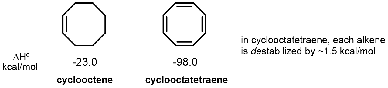
Benzene exhibits more stabilization per alkene than 1,3-cyclohexadiene:

On the other hand, cyclooctatetraene appears to be destabilized by conjugation:
Aromaticity and anti-aromaticity
Extra stabilization — or extra destabilization
This extra stabilization in cyclic π-systems is called aromaticity. On the other hand, extra destabilization is called anti-aromaticity.
Hückel’s (4n+2) Rule
Count the π electrons: 4n+2 or 4n?
Hückel’s (4n+2) Rule can help determine which of these two categories a cyclic π-system belongs to.
Hückel’s Rule looks at the number of π electrons in a system and determines whether the value satisfies the equations 4n+2 or 4n. Here, n is any arbitrary integer, not a variable. In practice, this means cyclic π systems with 2, 6, 10, 14, etc… π electrons are aromatic, while cyclic π systems with 4, 8, 12, 16, etc… electrons are anti-aromatic.
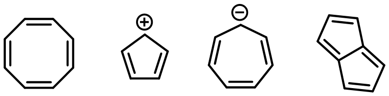
Aromatic systems are planar, fully conjugated systems with (4n+2) π electrons. They have a closed shell (all paired electrons) and are exceptionally stable. Here are examples:

Anti-aromatic systems are planar, fully conjugated systems with (4n) π electrons, and are exceptionally unstable. Molecules often deplanarize to avoid being conjugated and anti-aromatic. Here are examples:
Frost circle diagrams
Visualizing the MO energy levels
A Frost Circle molecular orbital diagram helps to visualize the relative energies involved. To create such a diagram:
- Draw a polygon matching the cyclic ring size with its vertex down.
- Each vertex = an MO energy level.
Here is an image of this method taken directly from Clayden 2e, page 160:
Spotted an error, or want a topic covered next? Let us know.